Fusion 360 Draw Lines Connecting Sketch on 2 Planes
You are here: Home / Fusion 360 / Sketching / How to Use the Line Command in Fusion 360 (secrets revealed)
Transcript:
By the end of this video, you'll have a solid understanding of the line command in Fusion 360.
The line tool is one of the most common sketch tools in any CAD program… and that's why there are so many ways to access the line tool in Fusion 360.
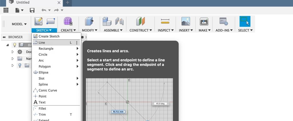
The line tool can be accessed from the sketch dropdown list in the model, sculpt, and patch workspaces. You'll also notice that the Fusion engineers have given the line tool the keyboard shortcut letter "L" because it is so frequently used.
Additionally, you can use the right-click menu. The line tool is under the "sketch" category or if you use the marking menu you can click sketch and quickly drag your cursor down through the line tool…clicking again to activate it.
With the line command active you can draw a line on any sketch plane or surface of a 3D model. Lines can be drawn between any two points at any length or angle needed.
I'll click on an origin plane to demo drawing some lines. To start any line you'll have to click the first point Creates a sketch point. More . As I drag my mouse cursor around you'll notice it can snap into the origin point, or it can snap into any of these grid elements. If your lines aren't wanting to snap to the grid you'll want to make sure you have the "snap to grid" turned on in the "grids and snaps settings" down below.
I'll click once on the origin point… and as I drag my mouse cursor out you'll see two numerical input boxes appear. The first input box Creates a solid box. Select a plane, draw a rectangle then specify the height of the box. More is the length of the line and the second input box is the angle of the line.
If I type out 30mm and move my mouse even the slightest bit, you'll notice the dimensions change. To stop this from happening you'll want to hit the tab key after filling out one of these input boxes. I'll type out 30mm again…followed by the tab key. If you look closely you'll see the lock icon now appears and I can move my mouse cursor around without having to worry about the dimension getting messed up.
Now I can either click to set the second point of the line or I can type out a degree in the degree input box. I'll go ahead and click at 0 degrees, creating a horizontal line.
There are two important things to take note of. First off, you'll notice a horizontal constraint was automatically applied to the line. If you're not familiar with line constraints, you'll want to check out the line constraint video that I'll link to down below in the video description.
Second, you'll notice that once you click the second point of a line, the line command is still active….which means that I can click again to place another line… and so on…
To leave the line command you can either select The selection mode controls how objects are select when you drag in the canvas. More the check mark, hit the escape key on your keyboard, or you can activate another command by selecting its keyboard shortcut or by selecting another command from one of the dropdown menus.
I'll hit the keyboard shortcut letter "L" again to activate the line command. You'll notice I can start a line at the end of a previously created line by clicking on its end point… and I'll just click again to set the second point of the line.
With the line command, you can also create arcs. I'll hit the escape key to exit the line command and then I'll hit the keyboard shortcut letter "L" to activate it once again. This time I'll click on the end point of a previous line and while holding down the left mouse button I will drag the cursor around without letting go of the mouse button…
You'll notice as I drag my mouse cursor around the line turns into an arc…and I can move it to either side… I'll go ahead and click on the first point of the initial line that I created. This turns the shape orange, signifying the shape is a closed profile… which means that all endpoints of the sketch geometry are connected.
It's also important to note the color of the lines. Almost all of the lines here are blue because they are not fully defined. This means that I can drag them around by selecting them and moving them. However, you'll notice the first line is black, which means it's fully defined. The first line has a horizontal constraint and a dimension applied to it, ensuring that it can't be moved anywhere.
As you can imagine, making your sketches fully constrained is an important part of mastering Fusion 360, or really any CAD program. If you're not familiar with this concept then be sure to check out the video that I link to in the description below.
The last concept I'll cover in this video is construction lines. I'll first create a few lines to divide up this sketch profile…
You'll notice as I hover my mouse around that each shape is now highlighted on an individual basis. Now there may be times you'll need to draw lines in sketches to help dimension or drive the shape or size of the sketch… and this is where construction lines come in.
If I wanted these inner lines to help drive this sketch without segmenting the overall profile… then, I would want to change these lines to construction lines. To do so, simply hold down the shift key and select all the lines that you want to change. Then you can hit the keyboard shortcut letter "X" or select "construction" in the Sketch dialog box.
You'll notice that construction lines are signified by dashed lines. I'll go ahead and add a dimension to one of these construction lines so it changes the overall size of the profile…
Now if I hover over the profile shape again you'll notice it highlights the whole profile shape.
If you want to create construction lines from the start you can make sure its activated in the Sketch dialog box before drawing the lines. You can also revert construction lines back to regular lines by selecting them and hitting the keyboard shortcut letter "X" or of course by turning it off in the Sketch dialog box.
In summary, sketching lines is an important part of any CAD program, which is why the line tool can be activated in so many different places. You can create construction lines to further control sketch geometry without segmenting any profiles. To take full control of your sketches you'll want to fully understand the power and the benefit of fully constraining and dimensioning your sketches.
Reader Interactions
Fusion 360 Draw Lines Connecting Sketch on 2 Planes
Source: https://productdesignonline.com/tips-and-tricks/how-to-use-the-line-command-in-fusion-360-secrets-revealed/
0 Response to "Fusion 360 Draw Lines Connecting Sketch on 2 Planes"
Post a Comment